PIC18 Based Word Clock
The Concept
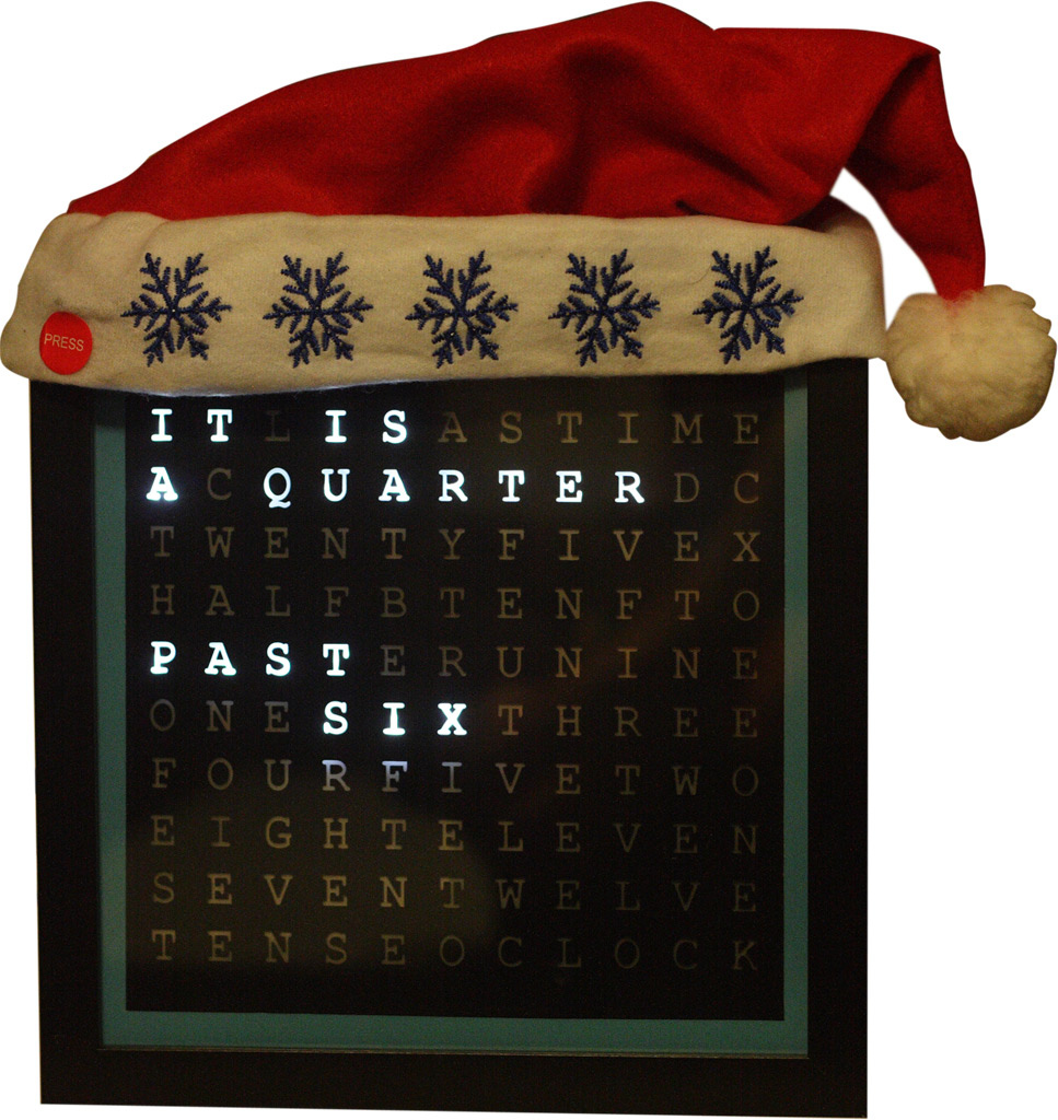
I set out in early October to design a Christmas present that everyone on my list would enjoy, and to make it reasonably priced enough to be able to build eight of them. I remember seeing a digital clock on thisiswhyimbroke that displays the time in words instead of numbers or other displays, and thought it was a really cool design concept (despite loving numbers as an engineer). Figuring that it could be built using an LED grid, some sort of letter grid to mask the LEDs, and a control board for a real time clock, I set out to build the $1100 clock for less than one tenth of their retail.
Electronics Design
The system was decided to have the following specifications:
- Be able to drive an LED grid containing up to 32 words. The words should have a brightness control as well as the ability to fade.
- Be able to keep accurate time using a real time clock (RTC).
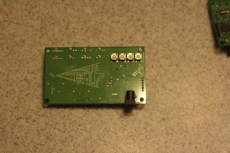
- Have four pushbuttons: two for setting the time, and two for setting the brightness.
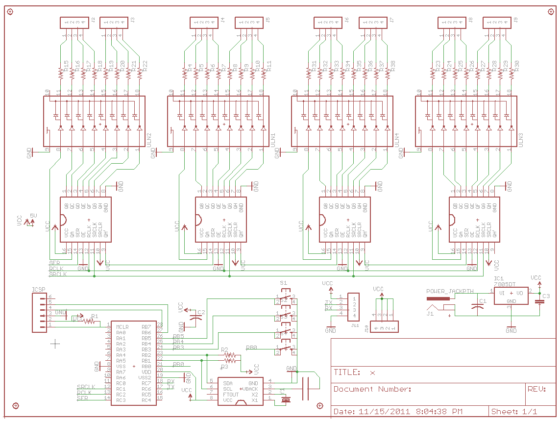
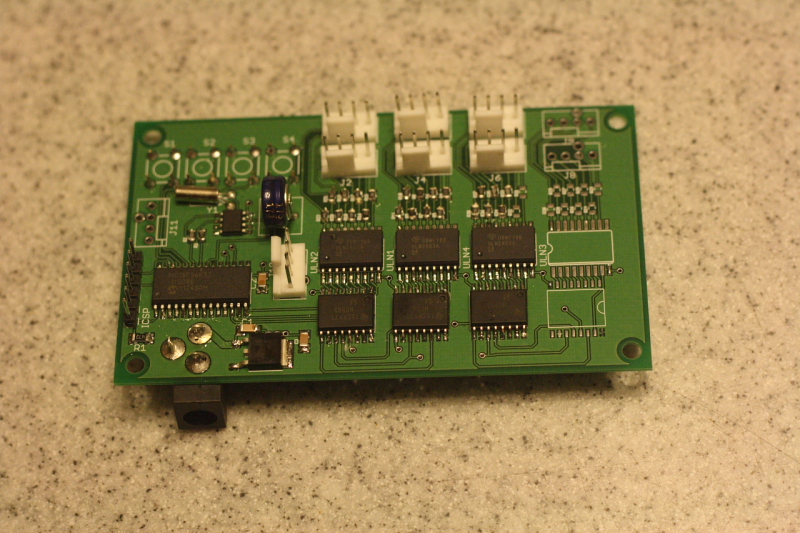
The main design consideration that had to be made was how to control the 100+ LEDs on the face of the clock. My first thought was to use the MAX LED driver used on the conducting robot, but $10 for 64 LEDs was out of my budget when each grid would contain more than 64 LEDs. Instead I took a transistor based approach which uses Darlington arrays to control clusters of LEDs. Darlington arrays are integrated circuits that contain transistors and biasing so that a voltage input, such as that from a microcontroller, can switch a pair of transistors on and off, essentially making these chips a multichannel on/off switch.
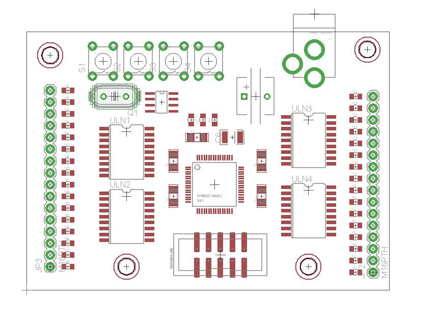
In this case, we do not need individual LED control, since individual letters will never be displayed without the entire word. The clock face that was chosen allows 22 words total, requiring a total of 22 control pins. Since the popular ULN series of Darlington arrays has 8 channels per IC, 3 will be needed per clock, but 4 were put on the board in case the design of the clock face changed to more than 24 words. This would require 32 pins to control all of the arrays. One problem with this is that a microcontroller would have to be selected with at least 32 pins GPIO in addition to the other functions the controller has to perform; meaning that over 40 pins would be required. Since breadboard versions of micros with more than 40 pins are rare if not impossible to find, I decided to use shift registers as an inexpensive way to add outputs without switching to a huge package size. The one downside is that these components do not have any hardware brightness controls, meaning that brightness would have to be controlled by software.
The next main component to chose was the real time clock. Although it was not a requirement, I wanted a RTC that could keep its time even when its power is cut. Because of this, I set out to find a real time clock that could work off of supercapacitors, and found the DS1340. The DS1340 is a real time clock with a trickledown charger which allows it to charge a capacitor so that when power is cut, it can use that capacitor as its backup source. The combo of one of these along with a .33F 5.5V capacitor (which can last 13 days without power – more than enough for shipping of these or just moving it from one place in the house to another) and 32khz crystal was under $5.
With all of the main components chosen, it was time to find a suitable microcontroller. The minimum requirements to meet the design specifications should be to:
- Have I2C for the RTC and UART for debugging.
- Have enough pins for 4 pushbuttons, a shift register interface (3 pins), I2c, and UART. This makes 12 total, 17 including power, ground, and programming.
- Be a PIC microcontroller (only because I already had a Pickit 3).
- Have a DIP package option, so that prototypes can be made on breadboard.
- Have at least 32K of memory, though it is hard to predict program size.
With all of this in mind, I wound up choosing the PIC18F26K22 – a 28 pin 8 bit microcontroller that maxes out at 16MIPS, has 64K of memory, and a price tag of under $3 for quantities of 10+. For a small production run like this, I decided it would be best to choose a processor that is overkill instead of finding out on December 15th that the program compiled to 33K or some internal EEPROM is needed along the way to retain data.
All of the other components were chosen to minimize size and cost. All coupling capacitors were chosen to be .1uF in a 1206 package (because I had these laying around). All resistors were chosen to be 0805, a compromise between the size savings of 0603 and the ease of soldering of a 1206. Since the number of LEDs coming back on each line differed from 1-7, different resistors had to be chosen to be placed between the grid and the Darlington arrays. I shot for roughly 5mA per bulb using the following equation, where N is the number of LEDs:
I=(5-3.2)V/(N*R)
- 1 LED -> 360 Ohms
- 2 LED -> 180 Ohms
- 3 LED -> 120 Ohms
- 4 LED -> 90 Ohms
- 5 LED -> 71.5 Ohms
- 6 LED -> 60.4 Ohms
- 7 LED -> 51 Ohms
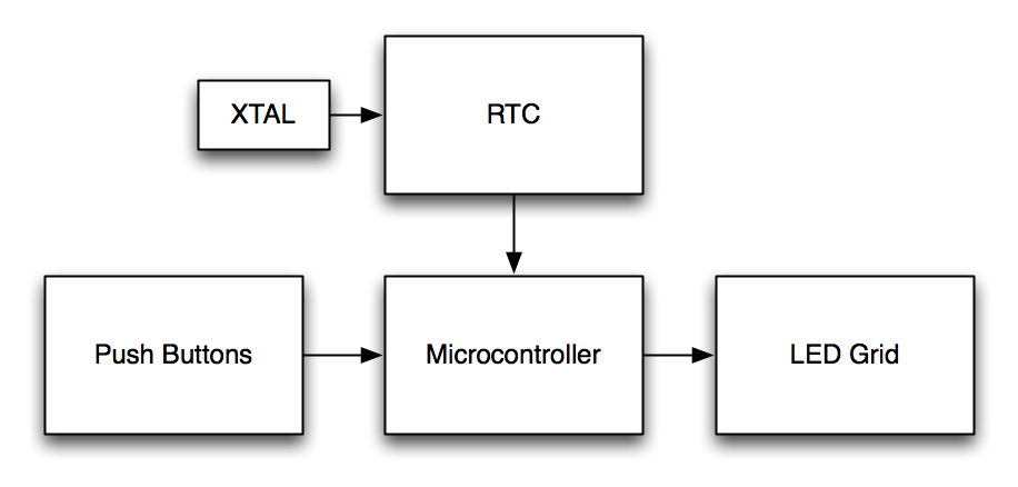
A complete parts list can be found later on, and the final system design can be shown below.
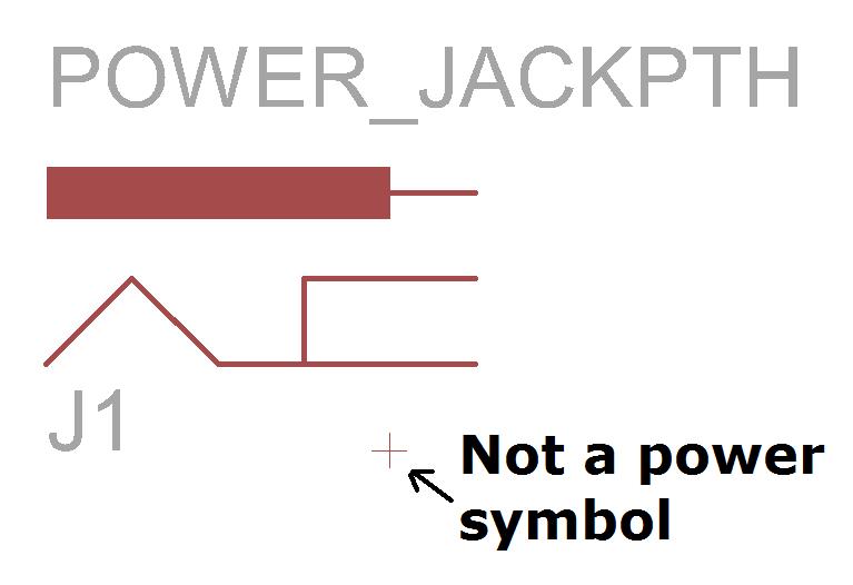
I got one board printed by BatchPCB to ensure that the design worked. Thank god I did this, because I reversed the polarity of the power connector because the EAGLE selection crosshair looked like a + symbol.
The final boards (10) were printed using RUSHPCB and worked out of the box (phew). The program that was created turns on the LEDs that should be on every 10ms, and then uses two comparators (one for fading and one for overall brightness) to turn them off between .1 and 9.9ms later to simulate brightness. The clock is read approximately once a second using a timer, and since the time updates happen every 5 minutes, no interrupt is fired since this is not a time crucial application. The program is run without an external oscillator. Full source code can be found below, with thorough documentation using Doxygen.
Enclosure Design and Construction
The final enclosure design was based off of this this Instructable which used an IKEA shadowbox with a mask printed on transparencies. Originally I was going to use Ponoko to have acrylic cut for the face plate and bamboo cut for the light grid and box, but $10 for the IKEA box could not be beat. They even come with a nice matte paper inside that can be cut and expanded to frame the printed transparencies.
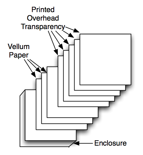
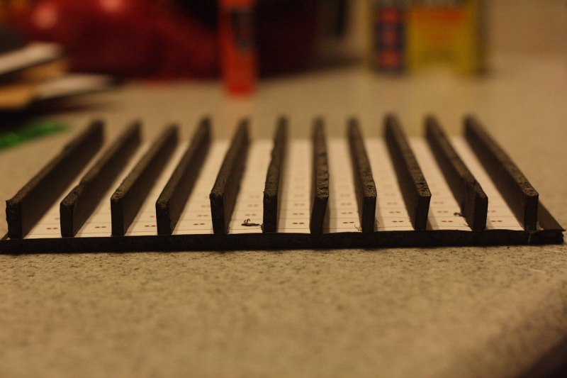
As for the masks themselves, using Adobe Illustrator ensured that the letter spacing would be correct when printed. It also allowed me to print out a template for the LED grids. The plan for the grids was to use a foamcore board, since it can be easily cut with an exacto knife but is still thick enough to be glued when making the light curtains.
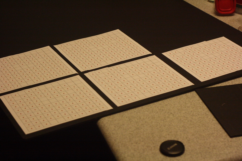
The light curtains were designed so that light does not bleed from one word to another. Because of this, they were positioned horizontally to separate rows, and then small spacers can be placed as needed to separate words in a row.
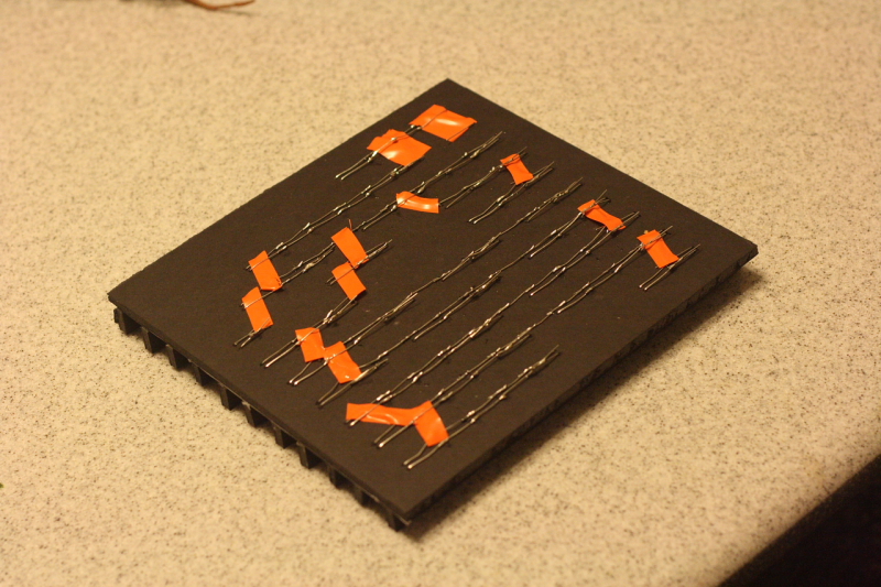
Finally, to connect the board to the grid, I decided to use some Molex connectors. Ideally, I would have loved a 32 pin connector, but pricewise it made more sense to get a bunch of 4 pin connectors and wire the grid that way. In total, each board had 8 connectors for the LEDs coming in, and 1 connector for power going out.
I honestly went in with no final plan to assemble all of this- just that I would have a control circuit that mounts to the back panel, an LED grid with a mask, and a Dremel to fix (see: demolish) anything that prevented everything from getting in the frame. I wound up placing the boards in the lower right hand corner of the box so that the power cable did not come out of the bottom, making the clock useful as either a desk clock or wall clock. To pad the LED grid from the walls of the shadow box, I cut up paper towel rolls and stuffed them in the sides like little cardboard springs. The big disappointment at the end was when I connected all of the Molex connectors and they were too thick to fit inside the shadow box. I had to go back and desolder all of the connectors on the boards, then cut all of the pins I had crimped off, wasting 20 connectors. All in all though, I finished 5 of the clocks for Christmas, and plan on finishing the final 3 after a break from engineering at home.
Future Considerations
If I were to do this project again, there would be several things that I would do differently. Now that I am more comfortable soldering fine pitches and using non-breadboardable components, I would swap the PIC18 and shift registers for an STM32 in a 64 pin package. This would save money, board space, and power consumption. Since the molex connectors did not fit in the casing, I would switch over to just rows of pins, which would again save space. By doing a rough sketch of these changes in Eagle, I found the new board would be approximately 6.5 square inches, a savings of about 2 square inches.