Reverse Geocache Project
A few years ago, my brother gave me a Christmas gift that consisted of a check tightly folded up and placed in a large box filled to the brim with packing peanuts. So naturally now that he is getting married, I decided it was time to return the favor by building a reverse geocaching box to hold his wedding gift. I decided to base my design off of Arduiniana’s Reverse Geocache project, but with some big changes to the electronics. Although I loved Mikal’s locking mechanism and idea, I did not like the electronics packaging inside of the box or the cost of using so many boards. When I set out to build my own, I decided that the entire project would be controlled by one single circuitboard that integrated the power management, LCD, GPS, and microcontroller into one package. Overall this worked very well, and even though I would change a few things if I were to do this project again, I gained experience and saved money by implementing this design.
Hardware
The Arduiniana Reverse Geocache electronics system used the following components, taken from Mikal’s website:
- 1 Arduino Duemilanove
- 1 USGlobalSat EM-406A GPS module
- 1 8×2 blue backlight HD44780 LCD
- 1 Hitec HS-311 servo motor
- 1 illuminated pushbutton
- 1 low voltage Pololu power switch
- 1 2.5mm female DC power connector
- 1 Adafruit Arduino prototype shield
- 1 ornamental box
I did not want to have to order components from so many different distributors, so I ordered the EM-406A and a small servo from Sparkfun and set out to get all of my other components from Mouser. In the end, my list of major components looked like this:
- Microcontroller- PIC18F26K22ISP (same as the Qlock-2 clone)
- LCD- Newhaven NHD-0416BZNSWBBW 4 Line, 16 Character
- Relay- Jameco JST-5V (had a bunch of these on hand)
- OR Gate- TI SN74AHCT1G32DBVR
Like I mentioned in the intro, my goal was to incorporate the entire control system into one circuit board. The circuit can be split into two main sections: the power control block and the main control block. The power control block can be thought of as the equivalent of the Pololu power switch above; its job is to provide some way for the user to turn the system on initially and also to allow the microcontroller to control its own power. It does this by using an OR gate in the following configuration:
When the relay is turned on, it provides power to all of the other components. The rest of the hardware is pretty straightforward: the GPS connects to the microcontroller over UART, the LCD is controlled by 7 GPIO microcontroller pins, the servo is controlled by a GPIO pin, and there is a second UART connector broken out to a Sparkfun FTDI board pinout for debugging purposes.
As for the battery itself- any medium sized (500mAh+) LIPO battery above 6V would work well. I happened to have an 11.2V monster around for a quadcopter, so I wound up using that. The typical battery drain is somewhere between 150 and 200mA, but this is only for a maximum of 3 minutes at a time. When the box is in standby, the OR gate uses only nanoamps of current which is negligible unless you keep the circuit plugged in for a long, long time.
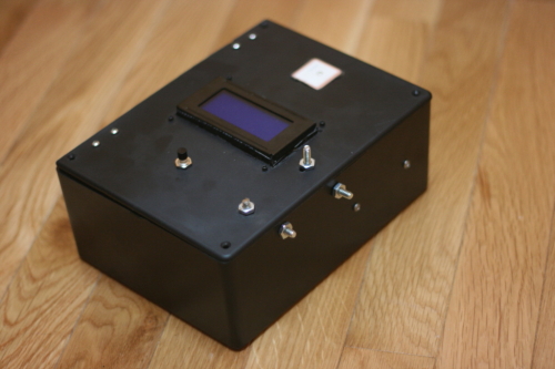
As for the enclosure itself, I used the (much uglier than Arduiniana’s box) plastic Radioshack enclosure to hold all these components. The locking system that I used was identical to the Arduiniana version- a couple of eyehole screws with a pencil connected to the servo to lock or unlock the box.
Software
The first thing that the software does is pull the output tied to the power block high. As mentioned in the hardware section, there is an “OR” gate that controls the solenoid that enables power to the main circuit, and by having the microcontroller pull one of the inputs of this gate high, it ensures that it will not turn off when the momentary push button is released. After this there are quite a few initializations for libraries and peripherals, and then the main while loop is entered. In this loop, the GPS library checks to see if there is data to be parsed, and if so it parses the data. There is a timeout set in the program of 180 seconds so that if the on button is accidentally pressed indoors or somewhere else where the GPS cannot acquire a signal, the program will terminate without draining the entire battery. The GPS library will continue looking for a valid fix during this main loop, and while it is not found it will continue to count the timeout timer down.
Once the GPS location fix is valid, the program will compute the distance from the current location to the target location (as defined in GPS.c). Originally, I used the Great Arc formula to compute distance, but with 32 bit floats these values were often not as accurate as I would have liked. Instead, I created my own formula for computing distance based off of the latitude and longitude of New Jersey where I live. I found that every degree of latitude correlated to 69.172 miles and every degree of longitude correlated to 52.205 miles. The distance between latitudinal degrees will be the same everywhere since these lines are concentric, but the distance between longitudinal degrees will vary based on your latitude since longitudinal lines converge at the north and south poles. To find what distance a degree of longitude correlates to at your coordinates, simply multiply 69.172 miles (the distance between longitudinal degrees at the equator) by the cosine of your latitude. For example, I am at roughly 41 degrees North, so I would multiple 69.172 by the cosine of 41 degrees to arrive at 52.205 miles per degree longitude. If you use this code in your own project, be sure to tailor it to your location (unless of course you live in northern New Jersey, in which case you can just use these values and buy me a beer for using this code). Once you have the horizontal and vertical distances, you can use the Pythagorean Theorem to compute the overall distance. When working on a small scale (less than a few hundred miles), I think that this method works much better than computing great arcs, which are resource intensive and inaccurate when working with Microchip’s 32 bit float library. If the distance is less than a quarter mile, the box will open, otherwise it will tell my poor brother and his wife how far until the box will open.
There were 3 main libraries that were written in order to support this program structure: an LCD library, a GPS library, and a Servo library. Since a servo is looking for a 1-2ms burst every 20ms, the servo library consists of two timers that enable this behavior. The LCD library initializes the LCD by some predefined standards and then allows the program to write data to the LCD. The GPS library uses two ring buffers to receive GPS data and then parses it later when the processor is not in an interrupt. The GPS and Servo libraries both work off of interrupts instead of polling, so neither are very processor intensive. The code for all three of these libraries can be found on my Github.
Conclusion
I’d like to start this section by saying that I regretfully fried several things during this project. Things that cost more money than I’m ok with frying. Things that should have never been fried, if it weren’t for haste. If you look at the reference board, you’ll notice that there is a total of three power sources that can provide power to the 5V plain (Battery through the linear regulator, Pickit 3, FTDI board). This was a terrible idea on my part- I thought it’d be convenient for debugging but instead it just led to frying things when 2 sources were connected at once. The first casualty was the FTDI Breakout Board, which I was using to debug the GPS stream. I was powering the control board with the Pickit and plugged in the FTDI board and was immediately hit by that ever pleasant aroma of blue smoke. The Pickit shut off almost instantaneously but it was too late. The other casualty was an EM406 GPS module. After the first casualty I was dedicated to being more careful- I decided to only power the circuit from the battery. Unfortunately, I loaded up an old project file accidently in MPLab which had the Pickit supplying power, and when I connected them- GPS no more. This was 3 weeks before the wedding, leaving me frustrated, $60 poorer, and losing out on a week of coding while I waited for the new one. If I could make only one change to this board, I would add jumpers to control which power source was feeding the main power plane at any given time so that multiple sources would not short each other out.
The other major change I would make is that I would switch the relay used in the power control block with a transistor based power control method. During typical operation, the main control circuit draws somewhere between 150 and 200mA of current. The relay used here draws 100mA of current just to stay open- this works out to 33% of the total power consumption! A logic level MOSFET such as the PSMN6R0 would drain practically no current and would only provide 8mO of resistance from the drain to the source. This switch would save power, board space, and money.
Finally, one other minor design change I would suggest is mounting the LCD directly on the control board instead of requiring a harness. This would allow the electronics to package much more cleanly and save the time of building a 16 pin harness. I would also consider switching to a low power ARM Cortex chip such as the LPC800, LPC1114, or STM32F100 simply because I find them much easier to debug than PICs.
Overall this project was a success since the box worked as intended. My brother and his wife wound up driving around for 4 hours the day after their wedding trying to open their present, finally opening it at the top of my brother’s favorite hike. Isn’t engineering wonderful when it brings people together?
Check out the code today! https://github.com/Carrigan/PIC18REVGEO