555 Based Valentine’s Blinky Heart
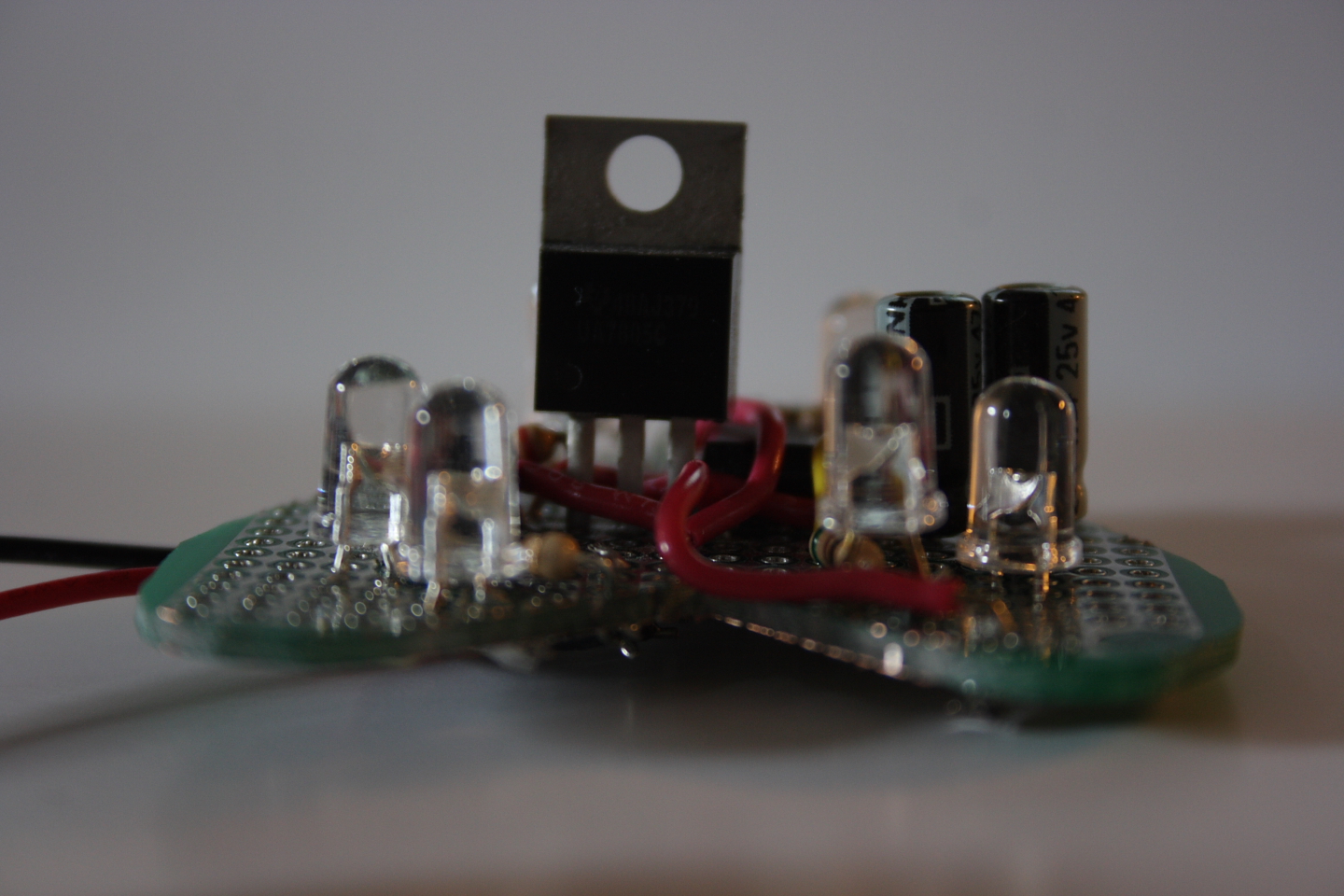
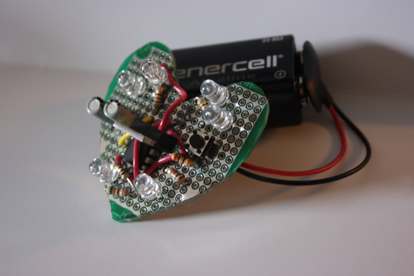
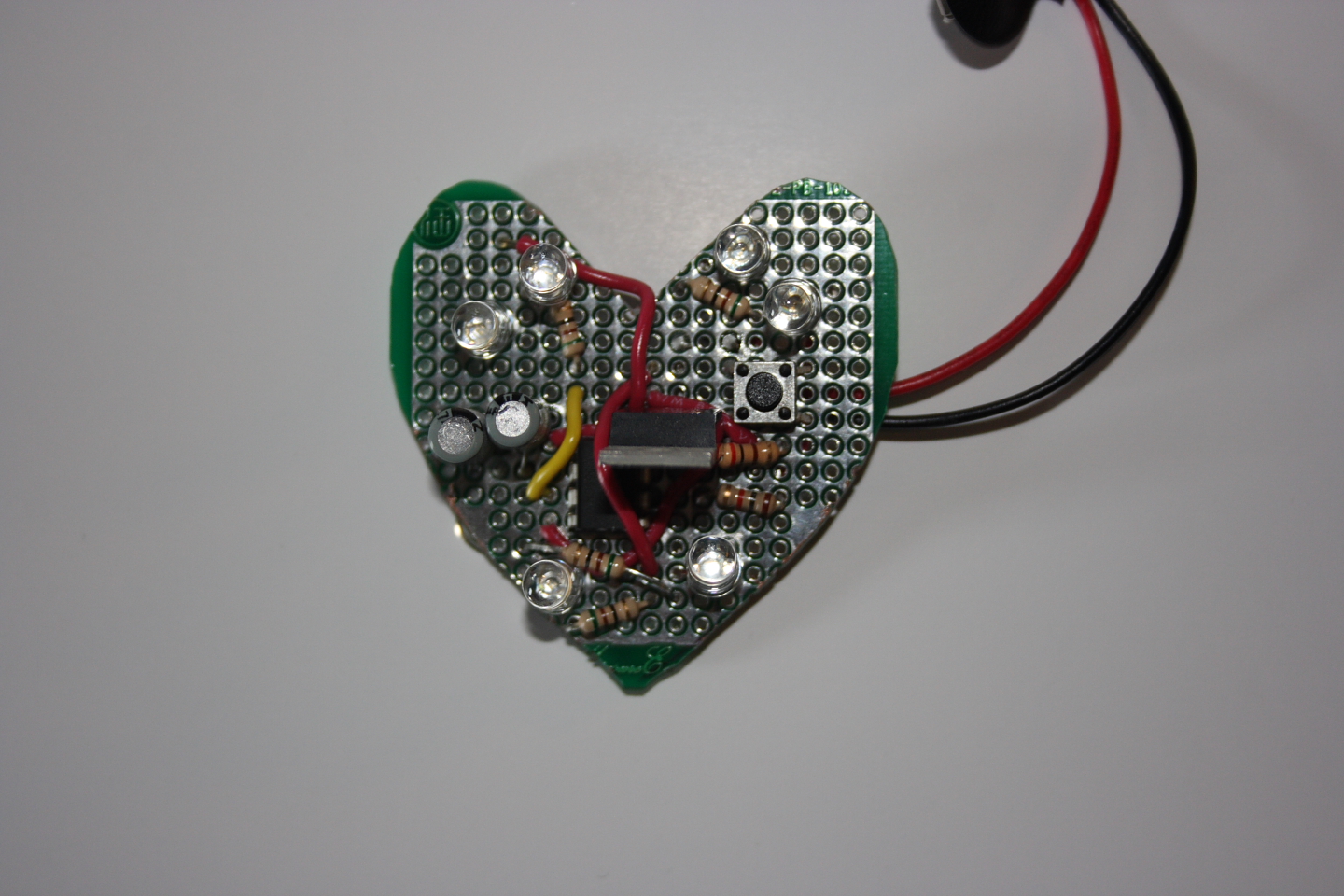
This year I decided to go with a little something different for valentines day. Every Electrical Engineer will tell you that the way to a girls heart is using LEDs, so I wanted to make something that would blink but with minimal hardware. I arrived at the idea of using a 555 timer to flash 2 sets of LEDs, and put these LEDs in a heart shaped PC Board. The whole board is powered by a 9V battery. The final product is shown below.
The 555 Circuit
Shown below is the circuit diagram for the EHeart.
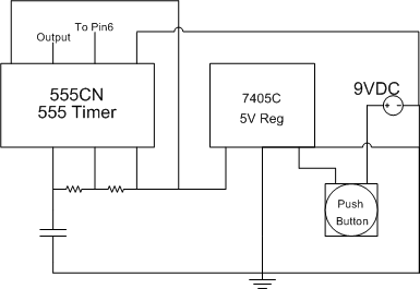
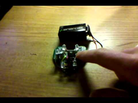
Let’s go piece by piece and examine what all of this is, and if this circuit is any good for other applications. First, the 9V battery is hooked up to the push button, which is hooked into a 5V regulator. This is why the circuit only runs when the button is pressed- when it is not depressed no current can flow from the battery. This is an excellent power switch since it does not allow standby loads and allows a very long battery life. Next is the 555 timer itself. The values for this are pretty much tweek-stimated, that is, I found whatever I could in the stock room and built according to that. I knew that I wanted approximately a .25s square wave, so I wound up going with a 94uF capacitor (well, two 47uF in parallel if you want to be specific) and 2k resistors. This gave an actual period of .38s, which is seen in the video above.
The Output
The output of a 555 timer is a simple square wave, meaning my device could have 2 states, when the output is high and when the output is low. I took advantage of this by hooking up 2 sets of LEDs as follows:
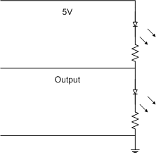
In this circuit, we’ll call the upper LED and resistor LED1 and the lower set LED2. When the output is high, LED2 is turned on since there is 5V flowing to 0V, and LED1 is off since both terminals would be at 5V. When the output is low, LED1 turns on since the 5V at its anode can now go to ground, but LED2 turns off since it is grounded on both sides. Resistors should be changed depending on your LEDs; I used 100ohms here for the purple LEDs. Aesthetics
This is where the fun comes in. You can make this circuit for basically any purpose; I will be making one for my bike soon for riding safer at night. In this case, I made the circuit in the center of a small circuit board, then used a dremel to cut a heart shape, and finally installed the LEDs in the remaining area.
There is plenty of room for tweeks to this. For the bike circuit, I will be using a switch instead of a button so the lights stay on. You could also make other circuits in the center- one great idea would be hooking up an accelerometer to LEDs on the sides of the heart so that it they light up based on how the board is held. You could do some pretty cool things with a microcontroller on board too (although you’d need a little extra space).